Modding NHeat - Cockpit

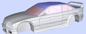
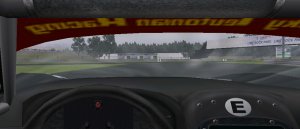
When going for making a cockpit, it's actually 2 versions of the same cockpit to be made. There's the cockpit that will be part of the car body's 3D model high1-high9/low1-low6. And there's the cockpit that will show up in F1 view mode in NHeat - this one is to be stored in high0.mod/low0.mod.

The latter one has to be much more detailed than the one that goes with the car body's model. With some other game engine mods, sometimes there's only the high detail cockpit for any view - this could be done for NHeat as well, but it's not recommendable, as it will heavily increase the poligon count on all cars without need

We'll assume that in this example our car model doesn't have any kind of cockpit yet

Typically the cockpit's 3D model is derived from the car's body, with only deleting all those parts outside the cockpit itself that won't be visible from the inside such as the car's rear, bottom and sides.

  1. Open the car body 3D model source file
  2. Copy of the car body's object to a new object
  3. In Face mode, select and detach (Create... -> Objects ... -> Detach) all what's hood and windshield from that copy
  4. Use Modify... -> Reorient on the detached object
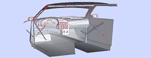
  5. Add new "inside" faces to get doors, bottom, dashboard, rollcage, etc
  6. Copy the detached cockpit object and the car body object to some new file cockpit.z3d, but stay on the original
  7. Delete all windshield faces
  8. Add some driver figure
  9. Now try to "rough" up the cockpit's ceiling; make it less smotth - adjust it's smoothness to what would be visible from the outside
  10. When exporting the car body 3D model, UniteSelect the cockpit to it
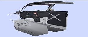
That's the basic steps to put some "external view" cockpit to the car. At least up to mapping it. The 3D model that had been copied to cockpit.z3d will be used for making the "internal view" cockpit
  1. Open cockpit.z3d
  2. On the car body object, delete every face that won't be visible from inside the cockpit from the driver's position. There should be little more left but a part of the hood
  3. Try smoothen every 3D structure in the cockpit. The mod users will have a very close look at anything from cockpit view, so things shouldn't look edgy.
  4. Adjust the driver's point of view in physics
  5. You'll have to export the cockpit to NHeat to check how it looks and if things are set the way you intend them to show up. For exporting the cockpit model, Create...-> Objects...->UniteSelect all objects in cockpit.z3d.
  6. Rename the resulting object to cpit[0]
  7. Export cpit[0] to high0.mod; copy high0.mod to low0.mod
  8. Pack high0/low0.mod to your CAR file and copy that to your mod's main folder
  9. start over at 1 until you're satisfied with the result, then start mapping the cockpit

To be able to use high res textures for the cockpit's interieur mappings, it's recommended to use a 1024x1024 TGA that has only all cockpit mappings. Parts that are visible from inside the cockpit should remain with high0/low0 and be mapped to mycar1.TGA (assuming the resulting car file's name is mycar.car).


Windshield or no windshield ?
There had been some discussions among modders if to have visible windshield in the internal view cockpit's 3D model or not. There was no final agreement on which way would be best. So you'll have to chose for yourself
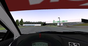
The advantage of having no windshield at all is that there's nothing that hampers the driver's views - and it saves some amount of work on making the cockpit. The disadvantage is that it indeed looks like as if there's no windshield...

If you want to add a visible windshield, there's some things to take into consideration:

  • The windshield will only be visible when environmental mapping is set for the windshield's mapping (Attributes....)

  • Unfortunatly NHeat only supports one environmental mapping file. NHeat's default environmental mapping looks great for glass, unless you have to look through that glas...

  • To avoid to almost blind the driver's view, you'll have to take care about how intense the reflection of light will be on the windshield by scaling the normals on the windshield's 3D mesh

It takes a lot of trial and error to get the windshield's glossiness look right and most likely you'll have to work out some mod specific environmental mapping.


Gauge mapping
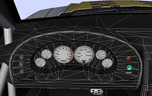
Even when using a 1024x1024 texture file for mapping the cockpit's interieur, most likely you'll have to scale down gauge textures to a size that will blur all numbers. At least, this will happen if you make the gauge textures be part of the dash texture. They simply will be too small to look crisp

If the gauges will be 3D structures of their own, their textures can as well have a different sizing than the dashboard texture. And even better, this would make adjusting the gauges' positions easier by far

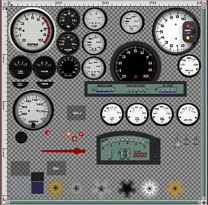
For Sportscar GTS and GroupC mods, the gauges' textures have all been packed to a single, alpha channeled TGA. These gauge textures then have been mapped to circular flat planes. The mapped planes could easily be moved on the dashboard for adjustment.

Another aspect was that this way each gauge's center was very easily be identified, helping for positioning the related dummy helper to the right place
Modding NHeat - Dummy helpers

While usually all 3D objects within a 3D model are static, it would be nice to have some of those objects being dynamic, moving. Which is what the so-called dummy helper objects are for.

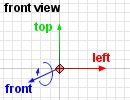
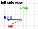
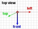
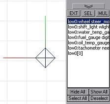
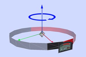
A dummy helper object is a pointed object of some kind, with it's edges pointing towards its coordinate axis. So moving or rotating a dummy helper object, you don't only move the dummy, but it's coordinate system as well. The dummy's coordinate system is shown by the narrow lines that spread from it's center
  • blue points towards the external object's front side (= z-axis)
  • green points towards the external object's top (= y-axis)
  • red points towards the external object's left side (= x-axis)
  

When rotating or moving a dummy helper object, take care ALWAYS only to do it in Object mode and that the action includes the dummy helper's coordinate system as well. The faces that you are actually moving are NOT really what the dummy helper is about - it's the dummy helper object's coordinate system that counts.

A dummy helper object always is a placeholder for some external 3D object (MOD) that is to be placed at the dummy helper's center. Furthermore, a dummy helper object always calls some certain game engine function that will be used on that external MOD. The dummy helper object's name in object list thus has to be special.
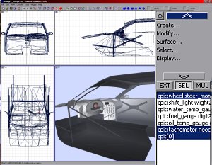
  • objectname:function external_object
objectname has to be identical to that internal object's name that the dummy helper is used on ! So if for example the cockpit object's name is cpit[0], the function to call be tachometer and the external object's file name needle.mod, then the dummy helper object's name has to be
  • cpit:tachometer needle.mod
However, by placing the dummy helper object you'd only define WHERE and WHICH function to use on what external MOD - but not how. The HOW is either to be defined in physics or it is probably hardcoded.

For use with the cockpt, there's 3 kind of functions available

  • rotate object around it's z-axis, hardcoded range
    • wheel

  • rotate object around it's z-axis, range defined in physics
    • tachometer
    • speedometer
    • fuel_gauge
    • volt_gauge
    • oil_temp_gauge
    • oil_pressure_gauge
    • water_temp_gauge

  • display static object on certain action
    • shift_light
    • fuel_pressure (not working ?)

The wheel model used with wheel dummy helper can either be some square flat plane, transparently mapped with some nice wheel texture. Or it can really be some 3D wheel model. Both ways are appropiate to get a great looking result, if done well.

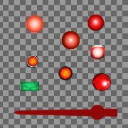
All external objects used with any functions except wheel usually will be some square flat planes with a transparent mapping; either some pointer texture (for all the gauges) or some flash light texture

Left image: Flash light and pointer textures used on external objects called by dummy helpers in GroupC mod cockpits. Notice the background transparency (= alpha channeled TGA)

Modding NHeat - Digitach

By default all gauges used in NHeat are analog; some pointer moving in a circle on a circular display. These displays technically are only nonfunctional textures, all function is with the pointer. So if we want to have a digital tachometer, it's the pointer and the way it works that we have to have a closer look on

As mentioned before, in the cockpit's mod there's dummy helper objects which are placeholders for other external MOD objects that Heat will dynamically add to where each dummy helper is located. The external MODs centers and its x,y and z-axis orientation will exactly be the same that the related dummy helper object has

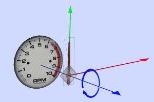
A dummy helper for a pointer needle function (such as tachometer) typically will have it's rotation axis (= z-axis) matching to the cockpit's z-axis. But as it's always the dummy helper object's z-axis being used for rotational movement, all we have to do to move the rotation axis is to move/rotate the dummy object's z-axis relation to the cockpit's z-axis.

So if we rotate the tachometer dummy helper object (and it's coordinate system, which is symbolized by the colored lines spreading from it's center) that way that it's z-axis matches the cockpit's y-axis (height), pointing to the cockpit's top, and replace the external pointer object by some band-like object, we'll get some kind of "treatmill" function.

If we now map that band's outside the way like shown in the image to the left and look at it's movement from inside the cockpit's x-axis (as any driver would do), we'll still have some kind of pointer. We just would have to take the texture's red/black transition for being the pointer.

Instead of rotating around a center it now looks like moving from left to right in a straight line - if the band's diameter is big enough. Which is exactly how any digital tachometer in NHeat works. It's still exactly the same way as any analog gauge's pointer, it's just its rotation axis has been rotated to the cockpit's y-axis, making it invisible for the driver's view and that way faking straight left-to-right movement.

The external "pointer" object doesn't need to be a full circle. Actually it only has to be a flat plane, if mapped right. But while adjusting the digitach's range, using a full circle can be very helpfull

Adjusting a digitach's range in physics can be quite a hassle for some reason though

  • The travel of the "digital pointer" will be much shorter than any analog tachometer's needle
  • It's much trickier to get the right coordinates of the "pointer's targets (start/end points)
  • The external "pointer" object must not show anywhere else than where it is intended to. Which sounds easier to do than it actually could be, as typically it likes to show up behind the dashboard
[ Cockpit/Gauges ]